240 V Single Phase 200 amp is common for USA new housing wiring.
I have two hot legs and a neutral coming into my breaker box. I have plenty of space for the clamps.
What size should they be?
One clamp per hot leg?
The big loads at my house are:
Heat pump with supplemental resistive coil heat.
Electric oven
Electric water heater
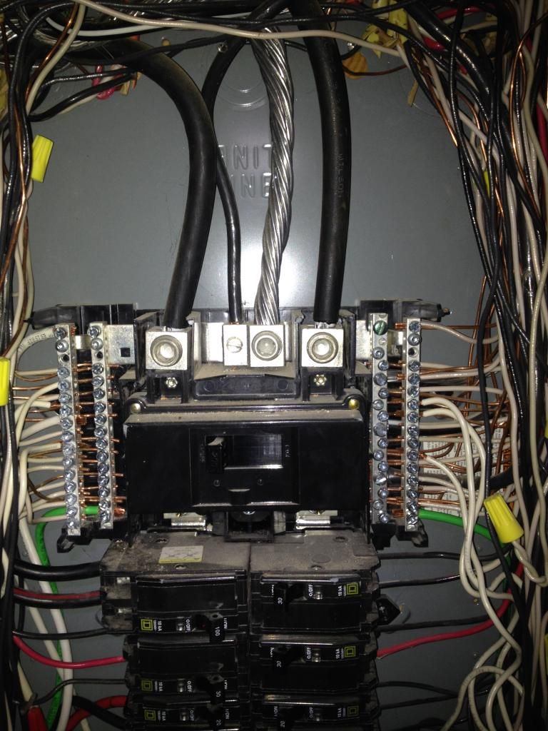
Image shows two hot legs going into main switch at top of breaker panel. The ground and neutral are between the two hot legs. Above the main switch, the hot legs go directly to the meter and through to the transformer without a customer-accessible switch.
http://i1296.photobucket.com/albums/ag12/hilltopmd/Solar/IMG_0850_zpsd6b...
Clamp data sheet http://www.hqsensing.com/download/3-1-1/2/%5B3-1%5D%202_2_2%20%2801%29%2...
You should indeed attach a clamp per hot leg and configure the voltage in the FLM to 120V. We typically advise to go for the 100A clamps for a dwelling in the US.
Great, I placed my order. I'll follow up with a comment on how the install goes.
On the order page it says I only need one of these clamps (and it is reporting ok with my FLM), so do I need to order another one?
This is standard US Single Phase 240V wiring.
Frank
I installed two 100A clamps, one on the left hot leg, the other on the right hot leg, The clamps were a close fit for the thick lines coming in from the meter. I connected them so the label faced toward the meter.
I connected the feeds to sensors 1 and 2 and set the sensors to single phase 120v 100A. The sensors report separately. When summed, they are very close to the consumption reported by my GE I210+c meter for 12/12/14.
On 14/12/14 I moved a clamp feed from sensor 2 to join the existing feed going into sensor 1, feed 2+ with feed 1+, feed 2- with feed 1-. I deactivated sensor 2. Result on sensor 1 was just the feed for the original clamp, not the sum of the two feeds.
Is there a way to connect the clamps to Flukso or configure sensor settings so I can get a single consumption number?
I have the Square D QO breaker box, which is the standard in USA. Other manufacturers mimic the design. The USA box seems substantially different from what I have seen in the Euro and Australian pictures. I don't see a way to physically get a single feed.
So you put the two clamps in parallel; have you ever played with batteries? What happens, if you put two batteries in parallel? Do the voltages double? - just do this little experiment that may answer what you experience (or consult a physics book)
With respect to the FLM: One port, one clamp respective pulse input (search the forum, why) - to add into a single stream, choose the configuration option "3 phases" in the sensor settings, then all clamp inputs add into one... (the manual may have told you the same - https://www.flukso.net/files/flm02/manual.pdf page 5, section 2.2.3)
Page 7, of course (grmph, that posts are still not editable) - and read "up to three phases" (Europe uses three), so don't mind to have only two... (one advantage Europe must have ;-))
The manual says "When selecting 1 phase, each clamp port will be sampled separately and mapped to sensors #1, #2 and #3 respectively." That is what I did initially.
Residential power in US is usually single phase/split phase. That is what I have. The feed from the transformer to the house is in the form of two 120v hot legs and one neutral. The neutral is tapped off the center of a 240v stepdown coil in the transformer. Normal (120v) circuits are fed from one of the hot legs and the neutral. High power (240v) circuits are fed from both hot legs.
I'll change the setting to three phase, move the feeds to 1 and 2 sensors and report back.
What do I do with the #3 clamp which is currently sampling the water heater?
BTW, I think Europe has the better approach to phasing and voltage.
Phasing/voltage - don't tell Edison ;-) (Tesla will cheer)
With respect to sensor 3 - good question, as here the behaviour of the v2b has changed; I assume (! - as I have a v2a) that if you changed to pulse/water this is not counted into the phases 1 and 2 - so just try it out and see what happens in the chart... (option is to look into the source code ;-))
Don't get me started on Edison.
Sensor 3 is on the electricity going to the heater. It needs to be analog. I was hoping to avoid having to look at Github resources such as code and board layouts.
What Flukso needs to be more useful in USA
1) Ability to measure consumption/generation/net flows when solar panels are connected to a breaker in the panel. The USA convention for household solar panel installation is to connect inverter output to an existing breaker in the panel. Open Energy Monitor, Smappee, and TED 5000 support this type of installation. Update the documentation accordingly.
2) Add split phase as a power option and update the documentation accordingly. Three phase works, but it a) isn't documented, and b) loses the ability to use the third analog sensor to measure something else.
3) Allow all sensors to be analog. Pulse measurements are not accessible to many USA homeowners. It would be useful and valuable to be able to use CT clamps to monitor more circuits.
4) Provide instructions on how to measure consumption by 240v appliances. These are usually the heavy energy users (heaters (of air, water, food), air conditioning compressors).